In this guide
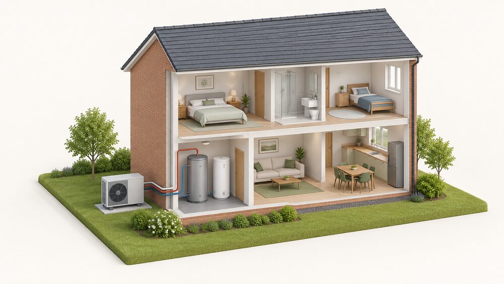
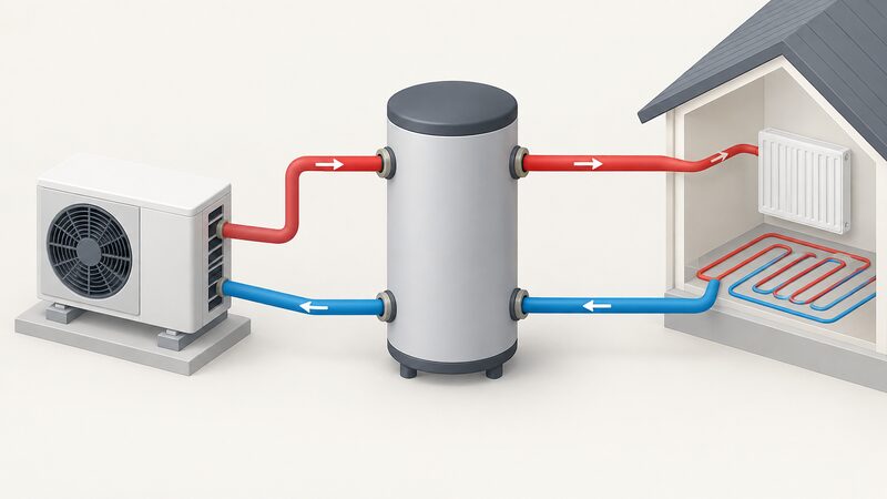
A buffer tank is a heated water vessel plumbed into a heat pump circuit to add volume and, in some arrangements, to separate one part of the hydraulics from another. It is not a hot water cylinder, and it is not a legal requirement. Whether a home needs one depends on how much water the system already holds, how the heating is zoned, and how the heat pump behaves at part load.
The reason the question comes up at all is that heat pumps generally operate at a lower temperature than boiler systems1, and they run for long periods rather than in short bursts. The Chartered Institute of Plumbing and Heating Engineering notes that not all types of heat pump will supply hot water, and the ones that do will not deliver it on demand in the same way or to the same temperature as a combi boiler, so a hot water cylinder is usually needed2. That cylinder is a separate item from a buffer tank, and the two are frequently confused.
Two functions: added water volume and hydraulic separation
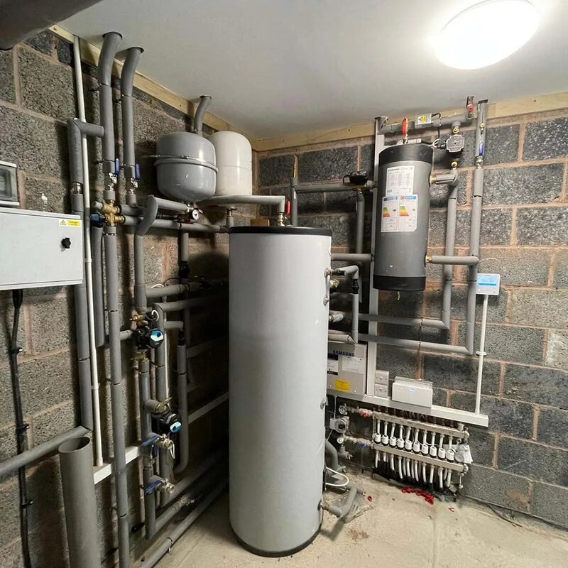
Everything a buffer tank does comes down to one of two jobs, and most of the confusion in the market comes from products that do both being sold as if they did one.
The first job is volume. A heat pump needs a minimum amount of water in the circuit so that it can run for a reasonable stretch before the return temperature rises enough to make it stop. The minimum water content is set so that cycling does not exceed six starts per hour5. Below that threshold the compressor starts and stops repeatedly, which is inefficient and hard on the machine. Adding a vessel of heated water raises the thermal mass of the circuit and stretches the run time.
The second job is hydraulic separation. Where the heat pump's own pump and the distribution circuit's pump would otherwise fight each other, a buffer or a low-loss header lets the two sides run at different flow rates. This matters most where the system is zoned, because closing a zone changes the resistance the heat pump sees.
A volumiser does only the first job. It is a plain vessel, usually on the return, that adds litres and nothing else. A buffer tank is normally arranged so that it can do both, which is why the two terms are used loosely and interchangeably in conversation but not in design.
"A thermal tank (also known as a buffer tank or accumulator) will help regulate the fluctuating use of the different ener"
The distinction matters for metering as well as hydraulics. Ofgem's guidance on the Domestic RHI states that a buffer tank should not be confused with a domestic hot water cylinder, and that whether a meter is installed before or after a buffer tank may make a difference to the metering requirements9. A buffer tank holds water that is part of the heating circuit, not water that comes out of a tap.
When a buffer tank helps: zoning, part-load and short cycling
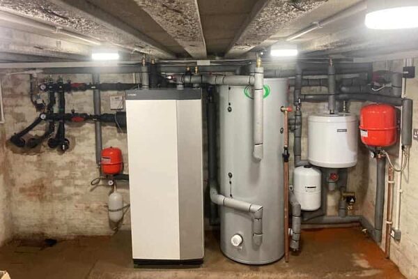
The case for a buffer tank is strongest where the system would otherwise cycle. A buffer tank can help stabilise hydronic operation, especially when zoning and part-load conditions would otherwise cause short cycling3. Those two conditions, zoning and part load, cover a large share of real UK installations.
Zoning is the more obvious of the two. A house with upstairs and downstairs zones, or with a separately controlled extension, will spend much of its time with part of the circuit closed. The heat pump then sees a smaller volume of water and a different resistance, and the run times shorten. A buffer tank on the primary side absorbs that variation.
Part load is subtler and applies even to a single-zone house. On a mild day the heat pump only needs to deliver a fraction of its rated output, and a system with little water in it will reach its setpoint quickly and stop. The same house on a cold day runs continuously and has no problem at all. This is why a buffer tank can look unnecessary in winter and essential in spring.
Defrost behaviour is a third case, specific to air source units. A buffer tank can help with defrost-related operation and affect overall efficiency in certain air-source configurations3. During a defrost cycle the unit reverses briefly to melt ice off the outdoor coil, and it draws heat from the system water to do it. More water means less of a temperature dip across the cycle.
When a buffer tank hurts: standing losses, temperature penalties and no clear purpose
A buffer tank is a vessel of hot water sitting inside a house, and it loses heat. That is not a side effect, it is the physics. Building guidance is explicit that heat losses from hot water storage vessels are limited7, which is a recognition that the losses are real and worth capping.
The losses are not automatically wasted. A well-insulated vessel inside the thermal envelope releases its heat into the dwelling, where it contributes to the heating load for part of the year. The same vessel in a cold garage or an unheated loft loses that heat to a space nobody is trying to warm. Position therefore changes the arithmetic, even though the cylinder's own loss figure does not.
The second penalty is temperature. A buffer tank holds water at the flow temperature the heat pump produces, and it sits between the heat pump and the emitters. If it is plumbed so that it mixes return water into the flow, the temperature reaching the radiators falls, and the heat pump has to run hotter to compensate. That is a design error rather than an inherent property, but it is a common one.
The third problem is a buffer tank with no clear purpose. Where the system already has enough water in its pipework and radiators, and where there is no zoning, a buffer adds losses and cost without changing the cycling behaviour. The installer, together with the manufacturer's recommendations, decides whether a buffer tank linked to a heat pump system is appropriate and what size it should be4. That decision is a design judgement, not a default.
There is also an unresolved question about who carries the risk when a third party changes how a heat pump is run. There was not consensus on where the liability would fall if an actor who is not the heat pump manufacturer caused damage to the heat pump by running it outside of its ideal operating parameters12. Controls that override the manufacturer's settings sit in that gap.
Sizing: roughly 10 to 20 litres per kW of heat pump output
Sizing starts from the heat pump's output, not from the size of the house. The working rule is roughly 10 to 20 litres of added volume for every kilowatt of heat pump output, which gives 100 to 200 litres for a 10kW unit. That is a rule of thumb for the added vessel, not a substitute for calculating the total water content of the system.
The figure that actually governs cycling is the total volume, which includes the pipework, the radiators or underfloor loops, and any volumiser or buffer. A system with large-diameter pipework and big radiators may already hold enough water to meet the six starts per hour target5 without any added vessel at all. A system with narrow pipework and compact emitters may need a substantial one.
Flow rate gives a sense of the scale involved. A heat pump with a 10oC flow and return difference delivering 16.75 kW moves 0.40 kg/s, which approximates to 0.40 litres per second5. Volume and flow rate together set how quickly the circuit's temperature responds when the compressor starts.
For comparison, the storage vessels in other heating contexts are much larger. Some hot-water tanks for system boilers can be 500 litres or more8, and one participant in consumer research described being told they would have had to store a big tank of about 300 litres13. Those are domestic hot water cylinders, not buffer tanks, and the sizes are not transferable.
| Item | Typical figure | What it is for |
|---|---|---|
| Buffer tank added volume | roughly 10 to 20 litres per kW of output | Raising total system water content |
| Cycling target | no more than six starts per hour | Setting the minimum water content5 |
| Example flow rate | 0.40 kg/s at 16.75 kW and 10oC Δt | Illustrating volume against flow5 |
| Domestic hot water cylinder | about 300 litres in one reported case | Storing water for taps, not for heating13 |
Placement and configuration: primary circuit, flow at the top, return at the bottom
A buffer tank belongs on the primary circuit, between the heat pump and the distribution system, so that it holds water at the temperature the heat pump produces. Placing it on the secondary side changes what it does and usually defeats the purpose.
The connection pattern follows the physics of stratification. Hot water is less dense than cold, so the flow from the heat pump enters at the top of the vessel and the return leaves at the bottom. That keeps the hottest water at the top, where it is drawn off into the heating circuit, and the coolest at the bottom, where it goes back to the heat pump. A vessel plumbed the other way round mixes the whole contents and delivers a lower temperature to the emitters.
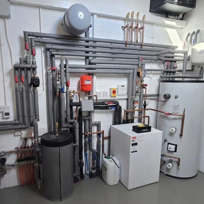
Two-pipe and four-pipe arrangements are the two common configurations. A two-pipe connection puts the buffer in series with the circuit, so all the water passes through it and the volume is added without separation. A four-pipe connection gives the primary and secondary circuits their own pairs of connections, which provides hydraulic separation as well as volume. The four-pipe version is the one that lets the two sides run at different flow rates.
Where a secondary heat source is involved, the control logic changes. A backup energy source is required when the required flow temperature is above the maximum flow temperature limit of the heat pump14. In that arrangement the buffer or header becomes the point where the two heat sources meet, and its volume and stratification matter more, not less.
Buffer tanks with monobloc heat pumps
Monobloc heat pumps keep the refrigerant circuit inside the outdoor unit and bring only water into the house, which makes them the type most often paired with a buffer tank or volumiser. The InstaGen IG4-MP1-A1, IG6-MP1-A1, IG8-MP1-A1, IG12-MP1-A1 and IG16-MP1-A1 are all described as monobloc systems15, and the Ideal Logic Air range is described as Ideal Heating's new range of monobloc heat pumps20.
Because a monobloc brings water indoors, the volume of water in the system is entirely a matter of the pipework, emitters and any added vessel. There is no refrigerant-to-water heat exchanger inside the house to buffer anything. That is why monobloc installations are the ones where the minimum water content question is asked most often.
Some monobloc units include circulation hardware as standard. The InstaGen IG4-MP1-A1 and IG12-MP1-A1 both list a primary pump built in15. Where the primary pump is inside the outdoor unit, the hydraulic separation question becomes more pointed, because the outdoor unit's pump and any secondary pump have to be reconciled.
| Model | System type | Primary pump |
|---|---|---|
| InstaGen IG4-MP1-A1 | Monobloc system15 | Built in15 |
| InstaGen IG6-MP1-A1 | Monobloc system17 | Not stated |
| InstaGen IG8-MP1-A1 | Monobloc system18 | Not stated |
| InstaGen IG12-MP1-A1 | Monobloc system16 | Built in16 |
| InstaGen IG16-MP1-A1 | Monobloc system19 | Not stated |
| Ideal Logic Air range | Monobloc heat pumps20 | Not stated |
Split systems, where the refrigerant circuit crosses the wall, are a different case and are covered separately in monobloc and split heat pumps.
Available types and capacities: wall-hung, floor-standing and integrated buffers
Buffer tanks and volumisers come in three physical forms, and the choice is usually driven by where there is space rather than by performance.
Wall-hung vessels are the smallest and are typically volumisers or small buffers. They suit a plant room or a utility wall where floor space is tight. Floor-standing vessels are larger and are the usual form for a buffer that is doing real hydraulic separation, because the four-pipe connection pattern needs height for stratification to work.
Integrated buffers are built into the heat pump or into a combined cylinder unit. Daikin's Multi+ domestic hot water tank is offered as 120L wall-mounted or 230L floor-standing21, and the same tank options appear on the four-port and five-port Multi outdoor unit pages22. Those are domestic hot water tanks rather than buffer tanks, but they show the pattern: the wall-mounted option is roughly half the capacity of the floor-standing one.
The outdoor unit's own size gives a sense of the scale of the equipment. The Daikin four-port Multi outdoor unit has a heating capacity of 6.8 to 10.0 kW22, and the Ideal Logic Air 10kW unit measures 1008 x 1095 x 518 mm and weighs 110kg20. A buffer tank sized for a unit in that range is a modest vessel, not a room-filling one.
Is a buffer tank always required?
No. A buffer tank is a design choice, not a regulatory requirement, and the decision rests with the installer and the manufacturer's instructions. What is required is that the system has enough water in it to run without excessive cycling, and that can be met in more than one way.
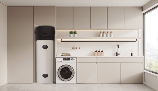
The related question that does have a firm answer is hot water storage. If you are replacing a combi boiler with a heat pump, you will probably need to install a hot-water tank or cylinder23. To provide hot water, heat pumps require a water storage cylinder, similar to older generations of gas boiler systems24. Consumer research has found that a heat pump installation requires a hot water tank, often replacing one that was removed to make way for a combi boiler after 200525. That cylinder is separate from any buffer tank, and the two should not be conflated.
There is also a misconception worth clearing. Heat pumps can work efficiently without much retrofit and insulation, but installers must choose the appropriate heat pump to match the property's characteristics26. The Welsh Government's guidance makes the point that the equipment has to suit the building, not that the building has to be rebuilt first. A buffer tank decision sits inside that same design process.
"Your installer, together with the recommendations of the manufacturer, will decide whether a buffer tank linked to your "
One operating difference catches people out. Heat pumps will need to be on all the time27, which is a different pattern from a boiler that fires for an hour in the morning and an hour in the evening. A system that runs continuously at low temperature has different cycling behaviour from one that runs in bursts, and that is the context in which the buffer tank question should be read.
What a buffer tank means for system design and efficiency
A buffer tank does not make a heat pump more efficient. It changes how the system behaves, and the efficiency effect depends entirely on whether the system needed the volume.
Where it helps, the mechanism is run length. Longer runs at steady low flow temperature are where a heat pump performs best, and the efficiency of a heat pump system will always be greater than 100% because source energy is not counted5. Heat pumps are up to 3 times more efficient than other heating systems6. A buffer tank that prevents short cycling protects that performance rather than creating it.
Where it hurts, the mechanism is standing loss and any temperature penalty from poor plumbing. Heat losses from hot water storage vessels are limited under building guidance7, which caps the loss but does not eliminate it. A vessel inside the thermal envelope returns most of that loss to the dwelling; one outside it does not.
The wider context is that heat pump installations have a quality problem. Poorly designed installations, inadequate heat loss calculations and rushed workmanship have left many households with systems that simply don't work as intended10. Support services now exist that cover error codes, flow temperature, weather compensation and heat pump performance28, which is a sign of how many systems need tuning after commissioning. A buffer tank specified as part of a proper design is one thing; one added to paper over a system that was never calculated is another.
For a household's energy independence, the buffer tank is neutral in itself. It does not generate anything, does not store energy across hours in any useful quantity, and does not reduce reliance on the grid or on a supplier. What it does is help the heat pump run well, and a heat pump running well is what reduces dependence on delivered gas, oil or LPG. The dependence that remains is the same as for any heat pump: electricity from the grid, a supplier, and a manufacturer's controls and spares. The vessel adds one more component to service and one more place for a leak, and it should be judged on whether the system needed it.
Sources28 cited
- Heat pumps, REA, 2026-09-17
- Heat pump systems, CIPHE, 2026-09-17
- Heat distribution, iDM Energie, 2026-02-10
- Thermal energy stores, Energy Saving Trust, 2025-05-15
- Domestic Heat Pump Guide, MCS Certified, 2024-04-02
- Your essential guide to heat pumps, Welsh Government, 2025-02-20
- Approved Document L, Volume 1: Dwellings, MHCLG, 2026
- What are the different types of boiler, Which?, 2025-09-16
- Domestic RHI: Guide to metering, Ofgem, 2026
- The growing problem of botched heat pump installations, Flexi Orb, 2025-04-02
- How to ensure a heat pump runs efficiently, Energy Saving Trust, 2026-05-19
- Summary of findings from heat pump flexibility expert workshop, CREDS, 2023-10-04
- Beyond affordability: why heat pumps feel like a gamble, Which?, 2026-07-02
- HEM TP 12: Heat pump methodology, MHCLG, 2026-01
- InstaGen IG4-MP1-A1 Heat Pump, Quiet Mark, 2026-09-17
- InstaGen IG12-MP1-A1 Heat Pump, Quiet Mark, 2026-09-17
- InstaGen IG6-MP1-A1 Heat Pump, Quiet Mark, 2026-09-17
- InstaGen IG8-MP1-A1 Heat Pump, Quiet Mark, 2026-09-17
- InstaGen IG16-MP1-A1 Heat Pump, Quiet Mark, 2026-09-17
- Ideal Logic Air 10kW Heat Pump, Quiet Mark, 2026-09-17
- Daikin 5-port Class 90 Multi air conditioner, Quiet Mark, 2026-09-17
- Daikin 4-port Multi air conditioner, Quiet Mark, 2026-09-17
- An introduction to heat pumps, Which?, 2025-09-22
- What impact can heat pumps have in domestic heating today, GOV.UK, 2023-11-21
- Seven reasons we still need heat pump subsidies, Nesta, 2025-11-20
- Pympiau gwres canllaw arbenigol ar gyfer perchnogion tai, Development Bank of Wales, 2024-11-07
- Energy saving myths, Centre for Sustainable Energy, 2026-07
- Wattson: a new kind of support for homeowners navigating heat pumps, Flexi Orb, 2025-06-23
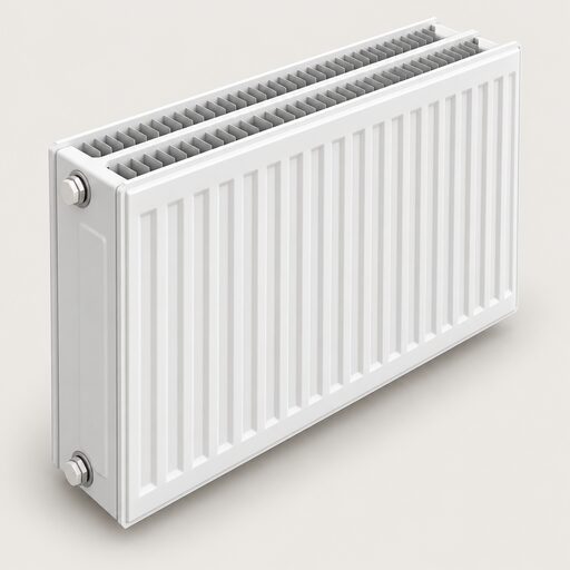 Radiators and Heat EmittersA radiator's real heat output depends on how hot the water inside it is compared with the room, so the figure in a catalogue often overstates what you will actually get.
 Radiators and EmittersWill your radiators still heat the house properly with a heat pump?
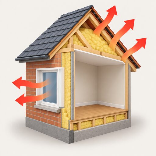 Sizing and Heat LossHow do installers work out what size heat pump your home needs, and why can a unit that is too big cost more to run than one that is slightly small?
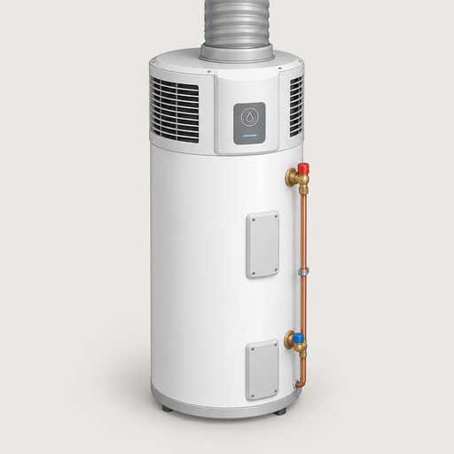 Hot Water Heat PumpsA hot water heat pump heats only the water in your cylinder, using air instead of a boiler flame.
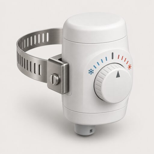 Hot Water Cylinder ControlsWhat temperature should a hot water cylinder thermostat be set to, and does it need its own timer apart from the heating?
 Insulation a Heat Pump NeedsWill a heat pump still work if your home is not well insulated, and would you need to add loft, wall or floor insulation first?