
In this guide
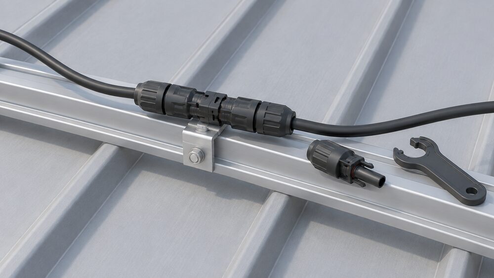
The DC side of a solar installation is the part that carries power from the panels to the inverter, and it is the part most households never see. It runs in direct current at voltages that can be lethal, it cannot be switched off by the consumer unit, and it is joined together with connectors that look identical across brands but are not interchangeable. The connector type most UK homes end up with is the MC4, a 4mm DC connector product range from Multicontact1.
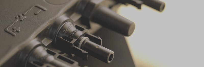
The standard behind it is IEC 62852:2014, Connectors for DC-application in photovoltaic systems, safety requirements and tests. It covers rated voltages up to 1,500 V d.c. and rated currents up to 125 A per contact, and it classifies these connectors as having no breaking capacity, though they might be engaged and disengaged under voltage1. That single distinction explains most of the safety rules around them: a connector is a joint, not a switch.
For a household, the DC side is where energy independence is most real and most fragile. Once the array is wired and isolated correctly, the panels generate without a supplier, a tariff or a fuel delivery. What remains is the inverter, the isolator, the connector brand and the competence of whoever assembled them, and those are the parts that decide whether the system runs for twenty years or becomes a fault-finding exercise.
What MC4 connectors are and where they sit in a solar installation
MC4 is not a generic term for any solar plug. It refers to a 4mm DC connector product range from Multicontact, and the name has since become shorthand for the whole family of single-contact DC connectors used on module leads1. On a typical roof, each panel leaves the factory with a male and a female lead already fitted. The installer's job is to join panel to panel in series until the string reaches the voltage the inverter wants, then run the resulting pair of conductors down to the inverter's DC input.
That places the connector at every joint in the array: between modules, at the end of each string, and at the transition from module lead to extension cable. It is a small, cheap, weather-exposed component carrying the full string current, and it is the most handled part of the system during installation and maintenance.
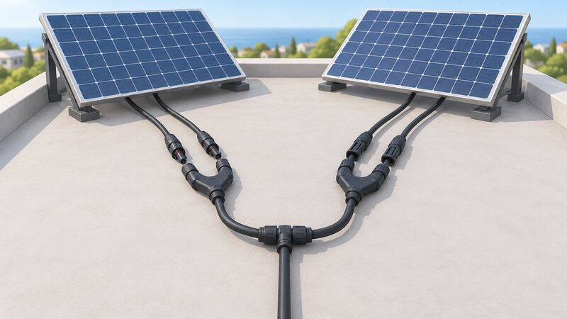
The connector family is described by its makers as suitable for solar installations, and Y-branch versions are designed to connect two solar panels in parallel to a single output4. That parallel function matters where an inverter has fewer input channels than the array has strings, which is common on domestic roofs with two orientations.
Where the DC side sits in the wider system is worth setting out, because the connector is only one link in a chain that runs from the module junction box, through string cabling, to a DC isolator, and then into the inverter. The solar inverters page covers what happens at the other end of that chain, and the solar PV safety page covers isolation and fire risk in more detail.
The standard behind them: IEC 62852 for PV DC connectors
IEC 62852:2014 is an International Standard published on 6 November 2014, first edition, running to 81 pages, under technical committee TC 82, solar photovoltaic energy systems. Its category is quality assurance and safety, and its keywords include rural electrification, solar power and LVDC1. It is the document that defines what a PV DC connector has to survive.
The scope is narrow and specific: connectors for DC application in photovoltaic systems, covering safety requirements and tests. It sets rated voltages up to 1,500 V d.c. and rated currents up to 125 A per contact, and it deals with connectors without breaking capacity that might be engaged and disengaged under voltage1. The standard is a consolidated version, meaning amendment content is incorporated into the publication rather than issued separately1.
UK practice reaches the same document by a different route. The interim product specification for plug-in solar states that all connectors shall fulfil the requirements of BS EN 62852, the British and European adoption of the same standard6. That is a useful signal: whether a system is a professionally installed rooftop array or a small plug-in kit, the connector requirement is the same.
The standard sits alongside a wider family that governs the DC side. PV modules themselves must fulfil protection class II according to BS EN IEC 61730-17, and fire classification work on plastic backed panels references class C under IEC 61730-28. The solar panel standards and testing page sets out how IEC 61215, 61730 and the rest fit together.
"All connectors shall fulfil the requirements of BS EN 62852"
What the standard allows: 1,500 V DC, 125 A and connections under load
The headline figures are easy to misread. IEC 62852:2014 covers rated voltages up to 1,500 V d.c. and rated currents up to 125 A per contact1. Those are the outer edges of what the standard addresses, not a description of a domestic string. A UK rooftop array typically operates at a few hundred volts and a handful of amps, well inside both limits.
The 1,500 V DC ceiling also appears in the Wiring Regulations. BS 7671:2018+A4:2026 covers installations at voltages up to 1,000 V AC and 1,500 V DC2, and Amendment 4 was published by the IET and BSI on 15 April 20269. The same 1,500 V d.c. figure appears in IEC 61140:1997, which gives it as a maximum DC voltage10. The convergence is not a coincidence: the connector standard, the installation standard and the protection standard are all written around the same DC band.
The more consequential clause is the one about breaking capacity. IEC 62852:2014 describes connectors without breaking capacity, while also noting they might be engaged and disengaged under voltage1. Read together, those two statements mean the connector can physically be pulled apart while the array is generating, but it is not designed to interrupt current as a switching device. Arcing at a DC joint does not self-extinguish the way it does on AC, which is why the isolation procedure matters more than the connector's voltage rating.
For scale, the currents involved in domestic DC wiring are modest. Guidance on plug-in solar limits the current at the point of connection to 3.5 A under all test conditions, at supply voltages of 0.94 Un, 1 Un and 1.1 Un where Un is 230 V6. That is a different circuit and a different purpose, but it illustrates how far a small domestic system sits below the 125 A the connector standard contemplates.
| Parameter | IEC 62852:2014 figure | Source |
|---|---|---|
| Rated voltage, maximum | 1,500 V d.c. | 1 |
| Rated current, maximum | 125 A per contact | 1 |
| Breaking capacity | None | 1 |
| Engagement under voltage | Possible | 1 |
| Publication date | 6 November 2014 | 1 |
| Technical committee | TC 82, solar photovoltaic energy systems | 1 |
MC4, Y-branch and extension cables: the connector family
The connector itself is only one item in a small kit of DC parts. The Y-branch pair is the one most often misunderstood. A pair contains two Y connectors, each configured as two male and two female inputs feeding a single male and a single female output, and the pair is designed to connect two solar panels in parallel to one output4. Certified versions carry TUV approval and are described as safe and water resistant4.
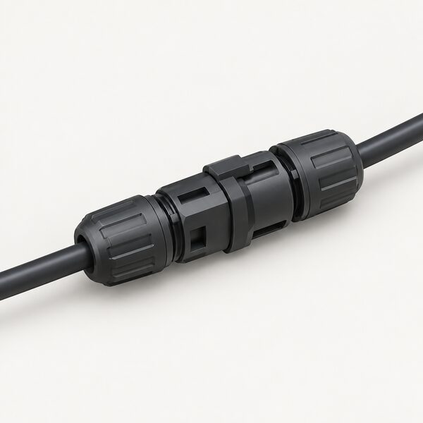
Extension cables do the same job over distance: they carry the string from the last module to the inverter or to a combiner point. The connector at each end is the same type, which is precisely where the mixing problem arises. Connectors that look identical across manufacturers are not necessarily intermateable, and the standard's requirements apply to the connector as tested, not to a mated pair from two different makers.
Cable selection is the other half of the family. Independent guidance on outdoor electrical runs notes that for longer runs or clipped to a surface outdoors, 10mm² may be required3. That is written for a different application, but the principle transfers: cable clipped to a wall or run over a long distance has different thermal and mechanical conditions from cable in free air, and the cross-sectional area has to suit the installation method.
Ingress protection is the third element. Guidance for equipment installed outdoors calls for a degree of protection of at least IP4X against solid objects and at least IPX4 against water3. Connectors described as water resistant by their makers are making a claim in that territory, and the IP rating is the language a specifier should look for.
DC isolators and combined AC and DC isolator units
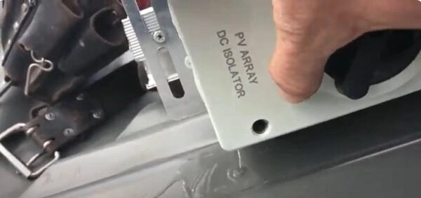
A DC isolator is a different device from a connector, and the distinction is the whole point of having one. A maker datasheet for a DC isolator describes it as a double pole breaker providing load protection and overload protection, mainly placed between batteries and hybrid inverters5. Double pole matters on a DC circuit because both the positive and negative conductors are live relative to earth, so isolating one leg leaves the other energised.
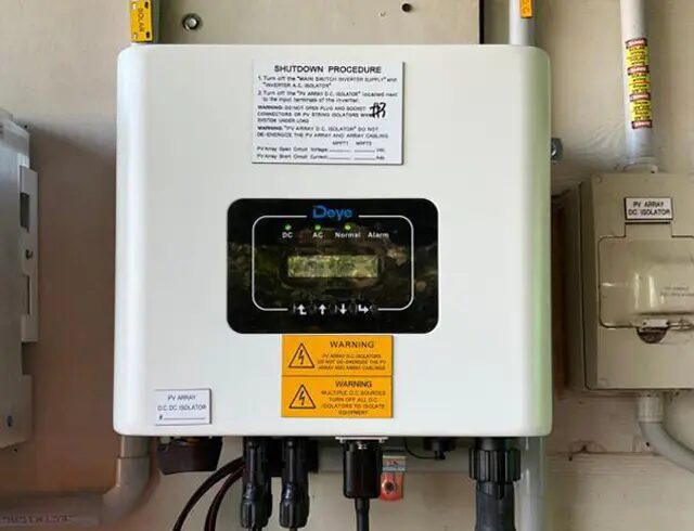
The placement described, between batteries and hybrid inverters, reflects where DC switching is most often needed on a modern system with storage. On a straightforward string array the isolator sits between the array and the inverter's DC input, giving a means of shutting the DC side down for maintenance or in the event of a fault. Combined AC and DC isolator units group both functions in one enclosure, which reduces the number of separate devices on the wall but does not change what each one does.
Isolation practice in the wider electricity network shows how seriously the principle is taken. Northern Ireland Networks describes a safe isolation service in which engineers disconnect power, remain while work is completed, and reconnect once safe11. The same network operator warns, in the context of service alterations, that a cable will remain a safety hazard because the supply cable will still be live and the power will not be turned off while work is done12. The domestic DC equivalent is that a string exposed to daylight is live whether or not the inverter is running.
Why connector choice matters for household energy independence
Energy independence on the DC side is genuine but partial. Once the array, the cabling and the isolator are in place and correctly specified, the panels produce electricity with no fuel input, no supplier involvement and no moving parts. The DC circuit is the part of the system that owes nothing to the grid.
What remains is a set of dependencies that connector and cable choices lock in. The inverter is a single point of failure and a proprietary device. The connector brand determines what can be replaced from stock and what has to be ordered. The isolator is a mechanical switch that will be operated rarely and may seize if it is not. None of these is a reason to avoid solar; they are the reasons the DC side is specified rather than improvised.
There is also a regulatory dimension. MCS certification governs the contractors who supply, design and install solar PV systems, and the Solar PV Standard MIS 3002 sets out those installation requirements13. The self-consumption guidance for MCS installers lists MIS 3002 alongside the battery storage standard MIS 3012 and the contractor certification scheme document MCS 00115. Product standards are moving too: MCS 005 Issue 4.0 is the Solar PV Product Standard, and a grace period was announced ahead of the implementation of four updated product standards16.
For households on lower incomes, the wider support landscape is separate from the DC hardware but relevant to whether a system gets installed at all. ECO4 places a responsibility on energy suppliers to help households in low-income areas heat their homes more efficiently14, and under ECO4 obligated suppliers are required to reduce heating costs for low income and vulnerable households by funding energy efficiency, insulation and heating measures17. Suppliers can also refer households under ECO4 Flex where they are struggling with persistent fuel debt or using pre-payment meters and have regularly been unable to stay connected due to financial hardship18. The scheme targets low income, fuel-poor and other vulnerable households19, and its flexible route covers SAP bands E to G for owner-occupied and private rented households meeting a combination of criteria20. ECO4 delivers measures to homes in Great Britain21, so Northern Ireland households sit outside it.
Independent advice has long flagged the gap this leaves. A Citizens Advice response to consultation noted the need for high quality independent advice about the changes consumers need to make their homes more efficient or to switch to a different heat source22. On the DC side specifically, the practical version of that advice is simple to state: the connector standard, the cable rating and the isolator are the three things that decide whether the array can be worked on safely in ten years' time.
Sources22 cited
- IEC 62852:2014 Connectors for DC-application in photovoltaic systems, IEC Webstore, 2014-11-06
- BS 7671:2018+A4:2026 Requirements for Electrical Installations, BSI Knowledge, 2026-04-15
- Section 722 EV charging complete guide, Elec-Mate, 2018-07-01
- MC4 Y connector pair, Robinsun, 2026-09-17
- UK Datasheet DC Isolator, GivEnergy, 2026-09-17
- Plug-in solar interim product specification (withdrawn), UK Government, 2026-06
- Plug-in solar final interim product specification, UK Government, 2026-07
- Fire spread over pitched roofs fitted with solar panels: summary, UK Government, 2025-12-22
- IET and BSI officially publish Amendment 4 2026 to BS 7671:2018, IET, 2026-04-15
- IEC 61140:1997 Protection against electric shock, IEC Webstore, 1997-11-26
- Safe isolation, Northern Ireland Networks, 2026-09-19
- Additional works, Northern Ireland Networks, 2026-09-19
- MCS launches new Solar PV Standard, MCS Certified, 2020-09-21
- MCS Solar PV consumer information, MCS Certified, 2026-07-30
- MGD 003 Solar PV Self-Consumption, MCS Certified, 2022-04-01
- Grace period for solar PV products announced, MCS Certified, 2026-07-30
- ECO4 Flex funding, Ceredigion County Council, 2026-09-17
- Energy Company Obligation: homeowners and tenants, Ofgem, 2026-09-17
- Energy Company Obligation guide, Uswitch, 2026-06-30
- Statement of Intent template, Ofgem, 2022-09
- Energy Company Obligation ECO guidance 2022-2026, UK Government, 2022-07
- Citizens Advice response on improving home energy performance through lenders, Citizens Advice, 2021-02-16
 Islanding and Anti-IslandingWhy do solar panels switch off in a power cut, and can you keep the lights on anyway?
 Fire and Electrical SafetyHow likely is a solar panel fire, and what actually causes one?
 Electrical Safety for GenerationWho signs off the wiring when you fit solar panels or a small wind turbine, and how do you know it is safe?
 AC-Coupled vs DC-CoupledCan you add a battery to your existing solar panels without swapping the inverter, and does one kind waste more of your solar power than the other?
 Cooling with Solar PanelsCan solar panels run an air conditioner, and will they cover the whole bill?
 Energy Bills and IndependenceSolar panels can cut the part of your bill that goes up with every unit you use, but you still pay a daily standing charge just for being connected to the grid.